AUTO BIM ROUTE TRAINING
Four simple steps to master the process
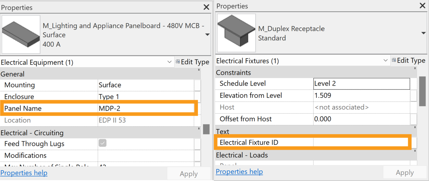
Place equipment in the model and make sure all of them have unique identifier under either Panel Name parameter (if electrical) or Electrical Fixture ID parameter (if loaded by Auto BIM Route)

If the equipment schedule is ready to use in Excel format, you can easily upload the file into Auto BIM Route. If the file is not ready, you still can upload routes information manually. Make sure the unique identifier is set for each equipment and the names in Excel file is exact match to all unique identifiers in the model.
After loading all routes into the software, you can use Preferred Area button to move or re-route any pipe manually to place it in the targeted area in your project. In order to use Preferred Area, you need to select the routes first (when selected they will appear yellow). This feature works by click and drag to draw a rectangular shape. This will force selected routes to pass through the rectangular shape created.
Note that all routes get pushed through the smaller dimension of the rectangular shape. Therefore, X or Y orientation of a Preferred Area will affect the direction of the route.
After finishing all 2D design creation process you can click on Process Route button to allow Auto BIM Route to find clash free placements for the selected routes.
You simply click on Show in 3D to see the results. You can always go back to Auto BIM Route and select routes that still need some adjustment and delete them by clicking on Delete 3D button. Now you can adjust the 2D again and reprocess routes in 3D as necessary.